Success!
As a part of the mobimower project, my goal was to implement centimeter level accuracy using GPS for navigation. Finally after months of research and failed experiments, today I was able to finally run my first RTK GPS test.
Need a clear day outside to run my field test now. Here is a quick brain dump of how it happened.
Watch out for errors I ran into:
- An Arduino sketch cannot be uploaded with the GPS HAT (shield) attached. you can either remove the Arduino pass thru pins on the TX/RX section, or remove the jumper on the shield itself. Bottom line, the Arduino TX/RX pins need to be exclusively available to the Arduino IDE.
- Make sure the Baud rate is set to 115200 for the shield within the sketch, as well as the serial monitor program on your laptop. I received gibberish for a long time until I figured out I was reading on the wrong baud rate.
- The GPS shield needs to be powered separately. it's possible the Arduino power out is not sufficient and once I add external power it can start working.
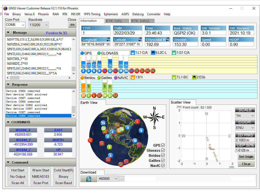
In any case, here is a snapshot and the video of the test.
3. The mobile phone is connected to the shield via Bluetooth. It is also configured with an NTRIP client that receives data from Ohio DOT's RTCM center in Lebanon, OH, providing the correction data for the GPS. Ohio DOT requires an application submitted via their portal to obtain a user ID and password to be able to use this. As long as you have an RTCM broadcaster within 10 miles and have credentials to use it, it will work.
4. The GPS unit is currently connected to one active antenna. Once I connect another antenna it will also be able to calculate the direction (heading).
5. The Arduino is currently running an NMEA parser program provided by Skytraq. I plan to get rid of it and use my own logic to reduce processing overhead.
With all of this connected, the GPS receives the GPS satellite data from the antenna, applies the RTCM correction data to increase the accuracy to 1 cm, and passes GPS data in NMEA sentences to Arduino via serial port. The Arduino takes this data and writes it to the USB port which is read by the python program on the laptop and displayed on the screen.
PS: The mobile phone is also set up to use NTRIP as a mock location app and hence use the RTCM corrected data from the GPS, with much greater accuracy.